Free GPS With Tire Purchase

Sunday, April 24, 2011

Alternators, Models & Design, Part 5, Delco 15 & 17 SI

The Delco models 15SI and 17SI are a larger version of the 10 and 12SI alternators.  Other than the part number, it is almost impossible to distinguish between the two, as practically all the parts are interchangeable between the two.  Pictured below is both models.  The 17SI is on the left and the 15SI on the right. 
You may notice some minor differences in the housings but both models could have any of the housings pictured.  Though they share the same basic design with the 10SI most of the parts will not interchange with it though.  The picture below shows how much larger the 15 and 17SI alternator is compared to the 10SI.

The 15 and 17SI units do not have the housing variations that the 10SI smaller units do, but they do have the terminal variations.  Testing this unit follows the same procedures as the 10 & 12SI units.  All terminals match the smaller units with the 'BAT' or battery terminal on the threaded post, the number one or spade terminal on the left is the indicator light and/or excitation terminal, and the number two spade terminal is battery sense.  The following paragraph for testing, is from the Delco 10SI post on 1/27/11.  For more detail information, refer to that older post.

Of course using a voltmeter across the battery terminals is the best way to check if it's working, reading a fully charged battery at 12.5 volts and then after starting the vehicle, it should read a volt higher.  Getting the alternator checked by a qualified technician is the best way to determine if it is good or not.  If the alternator is not charging, with the engine running, one test you can perform is to take a small screwdriver and poke it into the small 'D' shaped hole in the back of the unit (pictured illustration on the 10SI post) to bypass the regulator, which will put the alternator into full charge.  The grounding tab is about 3/4 of an inch from the back surface of the unit.  Don't poke it in too far or you can hit the spinning rotor, damaging the unit!  You do have at least an inch of space before hitting other components.  While grounding that tab, if the alternator charges, then the internal regulator is bad and will need replaced!

Thursday, March 31, 2011

Some People Shouldn't Work On Their Cars!

A guy came in the shop this week and after talking to him for 20 minutes, it was easy to tell that he should never go under the hood of a car!  It was obvious from his approach to his problems that all he's going to do is cause more damage to the vehicle and his pocketbook!

The vehicle in question was a late 90's Dodge product and he brought me the alternator to check to see if it worked.  The first clue of his ignorance was the fact that he cut the wires to the harness instead of removing a couple of nuts off the back of the unit and removing the harness.  Now when he patches it back, there will be another connection (probably a weak one to boot) and another potential problem in the future.  I tested the alternator and told him it was fine and that's when he told me what happened.

Apparently he was listening to the radio on the vehicle with the engine shut off and ran the battery down.  Now radios don't draw that much current so I asked him if he had turned the key to the 'accessory' position.  He said no because the radio wouldn't work in that position, so he turned the key to 'on'.  Maybe there are more people out there than I think there are, that don't know that when you turn the key to the 'on' position, you energize the whole electrical system, the vehicles computer, the ignition system and the fuel pump.  All this together will put quite a drain on a battery and run it completely down in a matter of a couple of hours, which in this case, it did as the radio faded out on him and the car was dead.

Well apparently he didn't know that and decided to get a jump start to get it going, but the idiot who jumped him (probably was as smart as he was, duh) hooked the cables up backwards.  Oh Crap!  Don't you people know just how much damage you can do to the electrical system on a vehicle by such a mistake?  Especially 2000 and later vehicles!  Well I'm not sure what all took place, but they did get the vehicle started.  The problem was, it wouldn't keep running when they pulled the jumper cables off.  To make matters worse, he told me that the gauges were flashing all over the place and nothing was functioning right.

Here's where 'old school' failed him, since he pulled the cables and the engine died, he automatically assumed that it's the alternator.  You've got a dead battery in the vehicle, that had been run down by leaving the key on with the engine off and you assume it's the alternator?  I guess the key word here is 'assume', you know, when you ass-u-me you make an ASS out of U and ME!  How in hell is the alternator going to work when the battery is dead?  It needs battery voltage to energize and his hooking up the cables backwards probably ruined the regulator, which controls the alternator and unfortunately is also located in this vehicles computer and not the alternator.

The first thing he should have done was get the battery charged and tested, or replaced it with a new one.  That may have solved all of his problems, if there wasn't any damage to the vehicles other electrical components.  It is possible that if the battery was run all the way down, by switching the cables on the jumping vehicle, he could have reversed the polarity in the battery which would change the batteries posts designations from positive to negative and vice-versa!  I wonder what damage they caused to the jumping vehicle too?  If they did reverse the polarity, that would also explain why the car died after pulling the cables.

I'm glad I'm not him, because all this ignorance could cost him upwards of $2,000 to properly repair it and get it back on the road!  He'll be lucky as hell if just replacing the battery fixes everything!  Warning, if you didn't understand any of this post, then stay out from under the hood of your car.  You'll probably damage expensive components if you try working on it yourself!

Wednesday, March 23, 2011

Either Feast or Famine!

Since last July, My business has been way off, which has kept me busy only half days.  But the two recent heavy snow storms, which dropped record snows in this part of the country, sank a bunch of the boat docks around the lake here.  Now there are hundreds of boats that went under water, all with starters and alternators that will need repaired.  Two of the marina's have already brought me quite a bit of work and a lot are waiting the insurance companies to come out and assess the damages and issue checks.  I heard one estimate of around 80 million dollars worth of damage around the lake.

So how does that affect me?  I now have loads of work and presently don't see the end of it for some time.  Though water getting inside of starters and alternators does not destroy these units and they will a lot of times function after their drained and dried out, or in some cases operate while still wet, they will eventually fail if not taken apart and properly cleaned up.  I much rather get a unit in immediately after it gets sunk, than to get it after it has set for months, as it can be easily disassembled and cleaned up.  Those units that come in after they have set for a while will be all rusted up and corroded and take much longer and be more expensive to repair.

Most alternators only need to be disassembled cleaned up and dried out and the bearings replaced.  Water usually doesn't affect the other components as long as there is not excessive rust or corrosion.

With starters though, they usually need the solenoids, drives and bushings or bearings replaced.  I can usually re-use the brushes if they are not worn down very bad.  I have to replace the solenoids because most of today's solenoids are rolled and sealed and they can not be taken apart and dried out like the older solenoids could.  I have to replace most of the drives as water gets into the roller clutches and will rust them up causing them to fail.  Most small shop rebuilders don't have the equipment to open these drives up and rebuild them.

Bottom line is if you have a unit that gets wet or goes under water, the quicker you can get it to me, the easier and cheaper it will be to repair!

Tuesday, March 15, 2011

Poor Quality, Part 5, Delco 22SI Truck Alternator

Last week a customer came in, in trouble as he was broke down on the road and just passing through.  He had this 130 Amp Delco alternator that had quit charging and he tried to take it apart to see if he could fix it, but couldn't get it together correctly and broke one of the brushes.

Generally, I would fault him for taking it apart without knowing much about them and causing damage, but there were several other issues with this unit that were not his fault!  This was a rebuild that he bought at a parts store in Chicago and he only got a thousand miles out of it before it failed.  The two major issues were that the ground screws that held the rectifier in were stripped when installed, causing the rectifier to get loose and arcing to the ground, blowing a couple of the diodes in it.  The other issue was that the rebuilder installed the wrong brush holder assembly causing miss-alignment of the brushes with the rotor.  The brush holder mounting bosses inside differ from the Delco 21SI alternator which looks almost identical on the outside.

I ended up putting a couple of heli-coils in the bolt holes, replaced the rectifier and put the correct brush holder in the unit to get him back on the road.  This was a needless repair and would have not been necessary if only the rebuilder had done his job right!  The stress of this repair was compounded by the fact that he stood right there and that I had trouble with the unit having to assemble and take it apart several times before I finally got it fixed!  If I had any idea who the original rebuilder was I would post his name and company here and warn everyone to stay away from him!!!

Thursday, March 3, 2011

Alternators, Models & Design, Part 4, Delco CS130

The Delco CS130 Alternator was the first of the Delco units that started to be designed for the engine compartment instead of being universal.  It came out in the late 1980's about when the cars went from a squared look to a more rounded aero-dynamic look.  They generally came in three amp ranges, 85, 100 and 105 amps, with the 100 and 105 amp units the most common.

Most all the units used the serpentine multi-groove drive belts, but can use the standard 'V' belt also.  After these alternators had been out in the field for a few years, they came out with heavier bearing units, as the bearings in the standard units were failing in rougher service.  There were several different drive end (front) housings used on this unit depending on the application, which made it quite difficult to substitute with a salvage unit.  The picture below is just a few examples.  Notice the two housings in the lower row in the center and on the right have heavier bearing bosses as compared to the other housings.
There were also a couple of differences in the bearing hole in the back housing as one used a corrigated metal strip to support the bearing while the other used a black plastic ring.  The plastic ring housing was the later version and it supported a heavier wider rear bearing and was used whether it had a heavy front bearing or not!

Internally, almost all the parts are interchangeable, that is they will fit most all the units, 'BUT' may not be correct or even function in the application.  For this reason, you must find the correct unit for the correct make, model and engine size.

The biggest difference is in the regulators.  Most of the regulators all look identical, but their internal circuitry were all different.  They all had the same four terminal plug in set, with one large terminal and three small terminals.  Besides other circuitry differences, the two main terminal designations were P-L-I-S which was an ignition controlled unit and P-L-F-S which was a computer controlled unit.  More recently the aftermarket has come out with a 'one wire' regulator for these units, which now makes this unit more versatile.

The main reason that about 90% of these units failed was the rectifier.  That component took and produced most of the heat in the unit and the OE diodes would only last so many cycles before they gave up.  Fortunately aftermarket heavy duty rectifiers were produced in the early 2000's, that made these units more reliable.  In fact, these rectifiers are so reliable, that I have never had a failure on any of them that I have installed, NEVER!

Tuesday, February 22, 2011

Can I Boost My Alternator To A Higher Output?

Like today, I occasionally get this question, as some people need more output due to extra loads put on the alternator by adding other electrical equipment to a vehicle that did not come factory installed.

This is no simple question to answer, as too many variables enter the equation.  First I'll address what happens to the unit by ramping it up.  Most alternators are pre-designed to put out the maximum amps for their size, though some of them can vary and accept a small increase in output.  Also, alternators are only able to maintain constant output at 75% of their rated capacity, which means it you have a 100 amp unit, you can only expect to use 75 amps 100% of the time.  Taxing the unit for more will result in premature failure!

The real problem lies in the ability for the unit to put out a charge, in all the engine speed ranges or RPM"s.  If you have an OE 100 amp alternator, that was installed in a vehicle it was designed for, it will function properly at engine speeds from let's say 400 RPM's at idle to 3,500 RPM's top engine speed.  Now let's say you need to raise the output from 100 amps to 160 amps output out of the same unit, and for this purpose, let's say the parts are available to do such a boost.  What happens is, by putting the heaver windings to increase the output, you will also move the RPM range.  Since the unit wasn't pre-designed to run with these heavy components, you now have changed the range, to where it may only charge from let's say, 1,000 RPM's to 4,000 RPM's, so at idle speeds, it will drop out and no longer charge.  You will also have to run the engine faster to get the output you want.

For most applications, parts are not available to rebuilders to boost most units beyond factory specs.  Each unit is unique to the application and very few or none of the parts on these units are interchangeable anymore.  There are companies that build OE style units into high amp output units, usually for stereo amplifier applications, but these units are usually short lived as most consumers of these units, tax them to their limits.  For this reason, I personally do not market or sell these units, nor will I stand behind them either.

An exception to this, is in older units that came in a large amp range.  Take the Delco 10SI for example.  It was produced by Delco in the amp ranges from 37 to 63 amps and has been boosted to about 80 amps without any problems either.  So let's say you have a 45 amp unit and want to boost it to 72 amps, the parts are available to do the job and you won't be pushing the design limits.  It will still function properly in all the RPM ranges!

One other minor problem worth mentioning is if you increase the output, you will also tax the engine horsepower a little bit, which may decrease the gas mileage some too.  Is the trade-off worth it?

Bottom line is if you need a large boost in amp output, you need to use a larger alternator that is designed for that output.  If you need a large output alternator, but only have room for a small unit, then don't expect the unit to function at idle speeds and don't expect it to have a very long life if you tax it close to it's limit!

Sunday, February 6, 2011

Alternators, Models & Design, Part 3, Delco 12 SI

The Delco 12 SI became the later, ramped up version of the 10SI.  This unit was used from the early 1980's to the late 80's.  Notice, I don't use specific years because some models used several different units during the crossover years. 

Though all the parts are somewhat interchangeable with the 10SI and a few with the 10DN, there were differences.  I've seen all the parts interchanged as some point or another and though they will work, they don't fit properly.  The 10SI's maximum designed output was 63 amps, but has been rebuilt to much higher outputs.  A big majority of the 12SI's were at 78 amps output and some were designed to give 94 amps.
Externally the main difference was the enclosed fan.  Behind the fan, the drive end housing had a raised ring that the fan meshed with.  This gave it more efficient cooling and I should mention that most all external fan alternators, cool by drawing air in from the rear of the unit, through the unit and out the fan, instead of pushing it through from the front!   There is also a larger cooling area on the back of the unit over the rectifier.

The 94 amp unit has cutouts on the drive end housing around the stator windings and it also has double angled cooling fins on the rectifier.  This makes it easier to identify when working on the unit.  Sorry, I have no pictures of the 94 amp-er.
Internally, the rotor and stator are thicker than the 10SI units and the rectifier has an extra grounding and mounting slot or hole.  I've had problems swapping a 12SI stator, putting it in a 10SI unit because the stator leads are not quite long enough and must be stretched and put in a bind to get connected.  They have broken in service, so I seldom do that anymore and only if necessary!  Hookups and testing are the same as on the 10 SI, so refer to that section for that information.

Tuesday, February 1, 2011

Alternators, Models & Design, Part 2, 10SI Variations

The Delco 10SI marine units have a screen behind the fan inside the case and a screened cover that covers the rear half of the unit.  This is to make the unit explosion resistant so if there is a spark inside the unit, it won't ignite the gas fumes that accumulate around the engine on inboard units.  The unit pictured below is a 'one wire' unit, but they do make a plug with two wires sticking out of it for regular wiring.  There is also a grounding tab and bolt just above and to the left of the battery post.
 
There is even an external regulated version that allows you to use the 10DN plug like the alternator on the previous post-part 1, where the regulator is removed and a terminal block is used in it's place.  Notice the spade terminals go in a different direction than in the regulated units. 

Other internal variations include regulators with 6, 8 and 24 volt settings and a reverse rectifier for a positive ground system.  The 24 volt works best with a stator and rotor that is wound for that output.  There are some units that have three spade terminals and the third one in the offset position is a stator tap, which is usually used to run an electric tachometer.  Another variation of this uses a post that goes into the hole labeled 'R' beside and above the battery post.  This can be added to any 10SI unit except marine!

Another variation uses modern produced housings for replacing other brand units.  The first one is a Prestolite replacement.  This unit also has screens for marine purposes as a lot of these particular units were used on boats.  This type of mounting may replace some foreign brand tractor units also, though lining up the pulleys can be a problem.
And this unit below is used for replacing Motorola units which are usually found on old tractors and equipment!

Thursday, January 27, 2011

Alternators, Models and Design, Part 2, Delco 10SI

Next in the Delco series is probably the most popular alternator of all time, the Delco 10 SI.  This alternator was the simplest in design, easiest and cheapest to repair and very versatile in it's applications.  GM started using this unit in all their vehicles in about 1972 and has been widely used in all sorts of vehicles, trucks, tractors both agricultural and industrial, and marine applications, up until the early 80's.  This unit is still in wide use today and is being rebuilt and/or reproduced even now.  I've built or rebuilt and sold a lot of these units myself, over the years!


Lots of you might recognize this unit, as the one they built a lot of 'one wire' units out of.  Many have used this unit as a replacement for equipment with bad wiring, on street rods, replacing generators on both vehicles and tractors, or any application that doesn't have all the proper wiring to operate wired units.  It's great for people who don't understand wiring and need something simple to hook up.  All that is needed is a wire connected to the battery post on the back of the alternator to the positive post on the battery.  That's it!  It's just that simple!  The unit grounds through the case, so if external grounding is necessary, there is a threaded hole in the back for a bolted connection.  I have never seen an isolated ground on this unit but that doesn't mean one hasn't been produced!

Converting one of these units to a one wire application is fairly simple, but sometimes not easy.  The only component that needs to be changed to make it a one wire, is the regulator.  The problems you can encounter is the properties of the stator and rotor.  There must be a tight clearance between these two components or it will have trouble self starting.  Another factor is the ability for the rotor to hold residual magnetism.  Some alternators will still work with poorer components, but you have to race the engine up to get it to energize.  In my experience, it's about a 50-50 shot, that changing the regulator will make one work as a one wire unit, without changing other components!  Usually if the unit is a one wire, there will be a black rubber plug capping off the two spade terminals. leaving only the post to hook the battery wire to.


In most applications, the terminal connections are easy to identify and are always the same.  The only exception is if the unit is built for an external regulator, which I will cover in the next post on variations.  The 'BAT' or battery terminal is of course the insulated post.  The two spade or regulator terminals are as follows, the number 1 terminal is the exciting and indicator light terminal.  This terminal must be connected to a switched source, meaning hot when the key is on and dead when the key is off.  It generally is also connected through an indicator light (or dummy light as it has been called), or usually some sort of resistor needs to be inline with this terminal.  It should not receive a full 12 volts as it was not designed that way.  The light bulb serves as a resistor which is inline with this terminal so sometimes if the bulb is burned out, the alternator won't charge!

Warning; If you connect this wire to the ignition coil, the alternator will feed back into the coil and you won't be able to turn off the vehicle, without grounding out this terminal or unplugging the harness plug from the alternator!

The number 2 terminal is a battery sense terminal, which senses the amount of charge that's in the battery and tells the alternator whether to charge more or less, controlling the output of the unit.  If you are wiring this unit up to something that doesn't have the proper harness, you can route this wire back to the battery terminal on the unit.  Though it's a viable solution, this is not the best way to hook it up because if there is any resistance in the battery wire, it may tend to run a bit hotter and overcharge a bit.

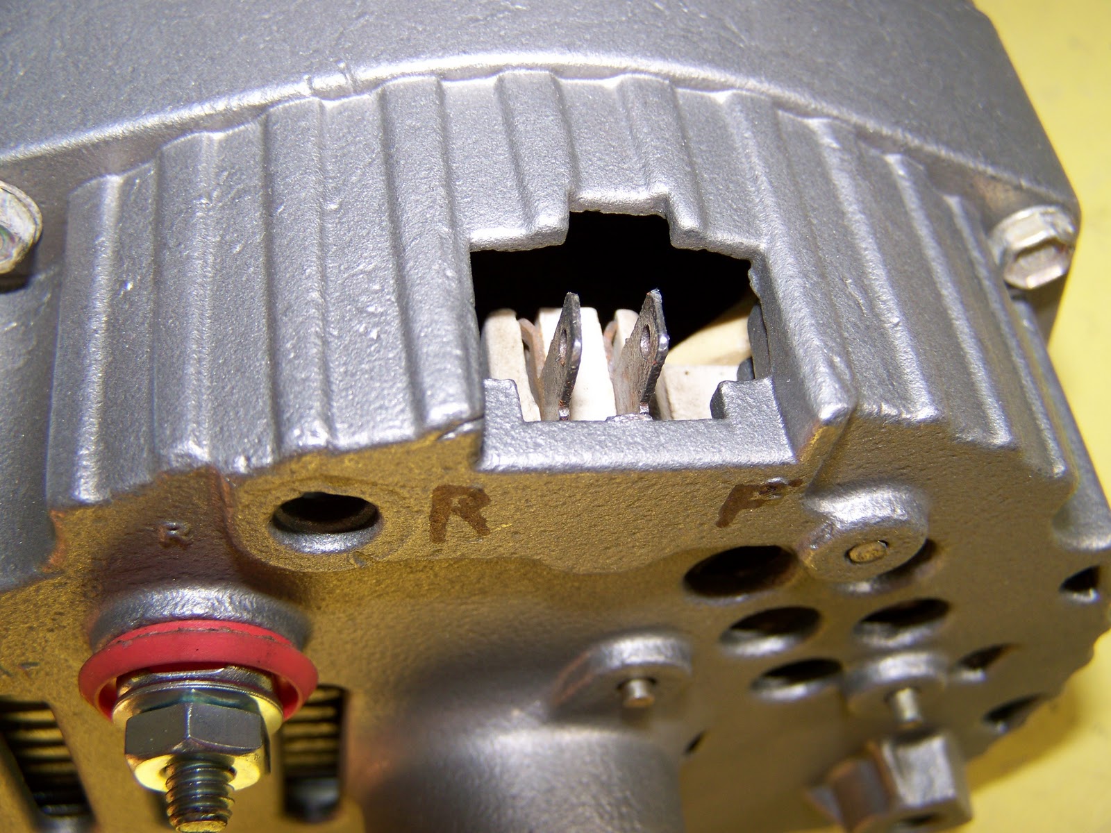
Testing the unit doesn't leave you many options.  Of course using a voltmeter across the battery terminals is the best way to check if it's working, reading a fully charged battery at 12.5 volts and then after starting the vehicle, it should read a volt higher.  Getting the alternator checked by a qualified technician is the best way to determine if it is good or not.  If the alternator is not charging, with the engine running, one test you can perform is to take a small screwdriver and poke it into the small 'D' shaped hole in the back of the unit (Illustrated below) to bypass the regulator, which will put the alternator into full charge.  The grounding tab is about 5/8 of an inch from the back surface of the unit.  Don't poke it in too far or you can hit the spinning rotor, damaging the unit!  You do have at least an inch of space before hitting other components.  While grounding that tab, if the alternator charges, then the internal regulator is bad and will need replaced!


Thursday, January 20, 2011

Alternators, Models & Design, Part 1, Delco 10DN

With this post, I'm starting a series of posts to help you identify the type and model of popular units and some advice on how to check them.  I however, will not be going into how to repair them.

I will start off with the Delco series of alternators and the earliest popular model, the 10DN.  The 10DN was the first widely used alternator on passenger cars and trucks, up until about 1971-72 and was an externally regulated unit, (no built in regulator)!


As you can see from the photos, it looks a lot like the next series of the most popular internally regulated units (next post) and though some of the parts are interchangeable, some are not.  The best way to identify this alternator is by looking at the back of the unit.


As you can see, the two wire plug in goes straight into the back of the unit and not around the edge like later units and is more squared.  You have, of course the 'BAT' or battery terminal on the left and a ground terminal 'GRD' on the right.  The ground is not often used as the alternator is internally grounded to the case.  There are however some applications where an isolated ground is used and that terminal is insulated from the case.

The two spade terminals where the wire plugs in, are the 'R' or stator terminal on the left and the 'F' or field Terminal on the right.  In most applications both of these wires go to the regulator.  The field terminal is where the regulator controls the output of the alternator.  Though it's not recommended, you can unplug these wires on the vehicle and get a short jumper wire and cross it over to the battery terminal, to check the alternator.  (Leave the battery wire connected!)  By doing this you are putting the alternator into full charge and run the risk of damaging a weak unit.  The battery terminal must have 12 volts going to it for the alternator to work.  If that wire does not show battery voltage then you have a wiring problem and need to trace it down!

To check to see if the brushes are functional, you can use an ohm meter to check for continuity from the field terminal to ground with the plug unplugged.  This won't tell you if the brushes are worn out or if the alternator is good.  It'll just tell you if that circuit is functional.

There are a couple of variations to this alternator, but are generally somewhat rare.  In a marine application, there are stud connections instead of spade terminals and it has an extension protruding from the rear bearing area.  There is also an agricultural application that has a mechanical tachometer drive, which is mounted on the back of the unit.  I've found these mostly on Allis Chalmers tractors, but have seen them on other applications.

There is also an optional external regulator available, that can be attached and bolted to the back of the unit, but it is generally more expensive than buying an internally regulated unit, so I don't do many of them.  The next series internally regulated unit is a better unit to work on anyway and is more economical too!

Wednesday, January 12, 2011

Need It Fixed Cheap!

In today's world of a declining economy, many people are forced to save money anyway they can.  This is also one of the reasons my business is off too.  I'm currently only working half days and closing my shop early in the afternoon to save on utility costs. 

Now I 'm getting more and more customers who say they need it fixed as cheap as possible.  They don't care if it's done right, just as long as it works for a while.  I really don't want to fix units that aren't properly repaired, because a lot of times they will come back to bite you.  So I usually state that by fixing it that way, I won't warrant any of my work on the unit, as some of the worn parts may damage my new ones.  On the other hand, if I want to fix it right and charge accordingly, I won't get the job or the money for the repair, because they don't have the money to spend.  So now I'm forced to take on more and more of these types of jobs.  Beggars can't be choosers!

Today I had a starter come in that the customer wanted fixed cheap.  The commutator on the armature was chewed up pretty bad and the brushes were worn out.  Those parts I had to fix!  The other parts that should have been replaced were the bushings, drive and solenoid.  The customer didn't want to replace those parts, due to the extra cost and they were still working and usable, so I reused them.  How long they will last is anyone's guess, but if the unit were mine, I would have replaced them.  Although, if I were in his financial condition, I might have done what he did!  So all I could do is repair it to his wishes and hope for the best! 

Tuesday, January 4, 2011

Does Checking Voltage Tell You If Your Alternator's Charging Properly?

In a word, No!

Now lets back up a second and say yes, you can tell if it is 'charging', but the question is, is it charging properly and does it have full capacity.  Checking voltage alone won't give you those answers.  You need to know the current output with and without a load to tell you if it is working properly.  There are even more sophisticated testing procedures that can be done, that tells you condition of various internal parts, but I won't go into that.

Usually I tell my customers, after I've checked or repaired their unit, to charge their battery fully.  Then check the voltage of the fully charged battery across the terminals and it should read about 12.5 volts.  Then start the vehicle and check again and the voltage should read about a volt higher or 13.5 volts.  Once the alternator has re-charged the battery, for what the starter used starting the vehicle, and if all unnecessary electrical loads turned off, voltage should approach the regulators set point of around 14.5 volts.  If you are still only reading battery voltage, then you may have a wiring problem, which is not connecting or energizing the alternator with the system. 

Getting back to our example of why checking voltage won't tell you what the alternators condition is, here is why.  On two separate but identical vehicles with 100 amp alternators, with regulators that have a set point at 14.5 volts, one of them is putting out 13.0 volts and when the current output is checked, it is shown to be putting out 20 amps.  The second vehicle is also putting out 13.0 volts, but the amperage output is 90 amps.  Both of these alternators are charging, but the one only putting out 20 amps is defective.  Why?  Because at a lower voltage, the alternators current output should be much higher to help build the battery closer to the regulators set point.  This lower output would indicate a bad stator or bad diodes in the rectifier and the alternator would need repaired.

I might also mention that if that 100 amp alternator is putting out 90 amps continues output and doesn't regulate down, it indicates either a bad regulator or a weak or bad battery.  If it is the battery, that alternator or it's replacement won't last long, because even though it is a 100 amp alternator, it can not continually run at that high of an amp output very long without burning up!  Alternators are only designed to run continuously at 75 percent of their rated capacity.  So a 100 amp alternator can only produce 75 amps of continuous output.

So just checking the voltage output may tell you that the alternator is working, but won't tell you if it is good!